Showing posts with label C07 (TechAnomalies). Show all posts

7.18 Why don’t the boot prints on the Moon match the spacesuit shoes?

IN A NUTSHELL: Because the astronauts wore overshoes when they walked outside on the Moon.


THE DETAILS: Doubters and conspiracy theorists are disseminating online the claim that the boots on the spacesuits used by the Apollo astronauts, currently stored in museums, don’t match the shape and sole pattern of the boot prints shown by NASA photographs (Figure 7.18-1).

Figure 7.18-1. An example of the conspiracy theory. The suit photograph is sourced from this article by Phil Plait.


Strictly speaking, this claim is actually correct: the boots of the Apollo spacesuits have a smooth sole and a heel, whereas the lunar boot prints have transverse ridges and no heel. But the Apollo astronauts wore overshoes during their moonwalks, and those overshoes match the prints.

Figure 7.18-2. Buzz Aldrin is about to set foot on the Moon during Apollo 11. NASA photo AS11-40-5866.


Figure 7.18-3. A detail of NASA photo AS11-40-5866, showing Aldrin’s overshoes.


These protective overshoes were worn over the regular boots, which were integrated into the spacesuit in order to provide an airtight seal. The sole of the overshoes was made of silicone, the upper was made of woven stainless steel and other thermal protection materials. Their main purpose was to protect the astronauts from the temperature extremes of the ground (hot in sunlight, extremely cold in shadow) and from sharp rocks.

The structure and engineering of the Apollo overshoes are described, explained and illustrated in exquisite detail in the book Moon Boot - The Story of the Apollo Lunar Overshoe by David H. Mather, which is available for reading online.

Figures 7.18-4 and 7.18-5 show one of Gene Cernan’s overshoes, returned to Earth after walking on the Moon in the final lunar mission, Apollo 17.

Figure 7.18-4. An overshoe worn on the Moon by Gene Cernan during Apollo 17, now currently owned by the National Air and Space Museum.


Figure 7.18-5. A bottom view of Cernan’s overshoe. More photos are available at the website of the National Air and Space Museum.


NEXT: Chapter 8. Alleged physical anomalies

7.17 How could a Lunar Module made of tinfoil withstand temperature extremes so well?

IN A NUTSHELL: That “tinfoil” was just its thermal blanket: there was titanium underneath. The LM could stand on the Moon with one side exposed to the sun and the opposite side in shadow without overheating or freezing because it was insulated by that highly efficient multilayer thermal blanket. This might make it seem fragile, but it was actually better protected against temperature variations than the rest of the Apollo spacecraft.


THE DETAILS: During the voyage to and from the Moon, the great thermal differences between the side of the spacecraft that was in full sunlight and the side in shadow required the astronauts to slowly roll the Apollo vehicle about its longitudinal axis to prevent it from overheating on one side and freezing on the other. This was known formally as Passive Thermal Control and less formally as barbecue mode.

The fuel tanks of the sixteen thrusters of the Service Module were in fact located close to the outer skin of the spacecraft and had to remain within very strict temperature and pressure ranges. The Command Module also has a heat shield which, if left to cool in shadow in space for more than thirteen hours, would have cracked and flaked with fatal consequences for the crew upon atmospheric reentry. The slow roll was devised as a solution to regulate the temperatures of these essential components of the Apollo vehicle.

The spacecraft, in other words, was extremely temperature-sensitive. Yet the Lunar Module, when it landed on the Moon, could no longer roll. It kept the same side exposed to the incessant heat of the sun and the opposite side exposed to the cold darkness of shadow for up to three days, without overheating or freezing.

This apparent technical contradiction actually has a very sensible explanation. Differently from the Command and Service Modules, the LM didn’t have to cope with the aerodynamic stresses of the liftoff from Earth (during which it was protected by a streamlined fairing), didn’t have a delicate heat shield to protect, and had no fuel tanks in direct contact with the outside skin. Accordingly, it could be equipped with a more effective thermal control system, which included a thermal blanket made of multiple layers of Mylar and/or Kapton. Spacers formed an insulating gap between the blanket and the pressurized crew compartment. The LM also had a sublimator similar to the one used for the spacesuits.

The apparently fragile, tin foil-like appearance of the LM was produced by this thermal blanket, which concealed the normal underlying metal structure shown in Figures 7.17-1 and 7.17-2 and in the illustrations of Figures 7.17-3 and 7.17-4.

Figure 7.17-1. A prototype of the Lunar Module, preserved at the Smithsonian National Air and Space Museum, reveals the metallic structure under the thermal protection covering. Credit: NASM.


Figure 7.17-2. A Lunar Module under construction, seen from the rear, before being covered by its thermal blanket.


Figure 7.17-3. One of the many technical drawings that describe in detail the structure of the Lunar Module. Credit: HeroicRelics.com.


Figure 7.17-4. A highly detailed cutout of the Lunar Module, published by Flight International, 6 February 1969. Scan excerpted from De la Terre à la Lune.


Moreover, the thermal blanket is not exclusive to the Apollo LM: it was used for decades by the United States’ Space Shuttles to protect the contents of its huge payload bay and is still used as an external shield by Russian Soyuz spacecraft, which spend up to six months in space, exposed unevenly to the heat of the Sun and to the chill of shadow in vacuum when they are docked to the International Space Station (Figure 7.17-5).

Figure 7.17-5. A Russian Soyuz spacecraft (TMA-7) photographed in space shortly after undocking from the International Space Station, showing the thermal blanket that covers it. NASA photo ISS012-E-24219, 8 April 2006.


China, too, covers its uncrewed Moon landers with a thermal blanket which is even more similar to the one installed on the Apollo Lunar Module (Figure 7.17-6).

Figure 7.17-6. The Chinese Chang’e-4 Moon lander photographed on the far side of the Moon by its rover, Yutu 2, in January 2019.


7.16 Why is there no engine noise in the Moon landing audio?

IN A NUTSHELL: Because the astronauts’ microphones were very close to their mouths, so as to cut out background noise, and were designed to pick up only sounds at close range, just like aircraft pilot microphones or mobile phone microphones. Anyway, in a vacuum the rocket exhaust doesn’t interact with an atmosphere, which is what produces most of the familiar roaring noise.


THE DETAILS: Bill Kaysing, in Fox TV’s Conspiracy Theory: Did We Land on the Moon?, says that “the noise level of a rocket engine is up into the 140/150-decibel range. In other words, enormously loud. How would it be possible to hear astronauts’ voices against the background of a running rocket engine?” Indeed, the recordings of the astronauts’ communications during landing and liftoff, while the rocket engines are running, contain no engine noise.

In the Lunar Module, the astronauts stood extremely close to the descent engine and the ascent engine is literally inside the cabin; yet there is no sign of engine noise in their radio communications.

This apparently unusual fact is actually quite normal and occurs not only in the Apollo recordings, but also in Shuttle or Soyuz liftoff recordings. Moreover, when we take a plane and the captain makes a passenger announcement, his voice isn’t drowned out by the noise of the engines, even though the same noise is audible in the cabin.

The explanation is quite simple: the closeness of the microphones to the mouth allows the voice to cover any background engine noise. The microphones used for space flights, in aviation and in mobile phones are designed to cut out background noise in noisy environments by picking up only sound sources that are very close. Bill Anders (Apollo 8, Figure 7.16-1) reportedly called them “tonsil mikes” because he said that he had to shove them down his throat to make them work. This allowed the voice to drown out the roar of the engines – if there was any to begin with. Kaysing’s claim is in fact incorrect: the noise of a spacecraft engine is not always “enormously loud”.


Figure 7.16-1. Bill Anders prepares for the Apollo 8 mission. Note the microphones on either side of his chin. NASA photo 68-H-1330.


When a rocket engine operates in vacuum, its exhaust expands without encountering any obstacle: it doesn’t collide at supersonic speed with an atmosphere and therefore it doesn’t generate the shockwaves that instead cause the loud noise that is heard on the ground when a large rocket is launched.

Both Apollo astronauts and current spacecraft crews report that when they are in space, sometimes they hear a bang at the moment of ignition, before combustion stabilizes, and they feel occasionally intense vibration; but apart from this, they say that the engines are noiseless. It seems unlikely that they’re all lying.


7.15 How come all the technical problems suddenly vanished?

IN A NUTSHELL: They didn’t. Problems occurred throughout all the missions and the first uncrewed flights were designed, as usual, to shake down the vehicles and correct or reduce their defects before the actual crewed missions were flown.


THE DETAILS: A recurring argument among hoax theorists is that the early Apollo missions were plagued with problems, leading to very public delays and cancellations, but all the troubles magically disappeared just in time for the flights to the Moon.

For example, Mary Bennett and David Percy claim that [the Saturn V] performed flawlessly throughout the entire Apollo program. But the early Saturn V F-1 engine tests were absolutely disastrous, with catastrophic explosions on the test stand.” They add that “The problem of combustion instability [...] known as the ‘pogo effect’ (the industry term for those internal oscillations we mentioned earlier) was in evidence from early testing of the Saturn rocket right through to the ‘Apollo 10’ launch – after which everything worked perfectly!” And Bill Kaysing asked “Why was Apollo 6, a total fiasco, followed by six perfect moon missions which in turn were followed by the manned orbiting lab debacle?”*

* Mary Bennett and David Percy, Dark Moon, p. 127-128; Bill Kaysing, We Never Went to the Moon, p. 8. The “manned orbiting lab” is Skylab.


Actually, if you check these claims against the mission reports, it turns out that the Saturn V’s performance wasn’t “flawless” at all. It always got the job done, but nearly all flights reported substantial problems.

Far from working “perfectly” after Apollo 10, as Bennett and Percy claim, the Saturn V was troubled by the pogo effect during Apollo 11 and 12 as well, leading to violent vibrations of the central F-1 engine of the first stage. For Apollo 13, vibrations were so intense that the central J-2 engine of the second stage had to be shut down automatically during ascent to Earth orbit to prevent it from tearing the spacecraft to pieces. Changes made for Apollo 14 finally made the problem manageable. Section 7.4 of this chapter covers in detail the major malfunctions and problems that affected all the Apollo missions.

As regards the “catastrophic explosions on the test stand,” that’s why rocket designers have tests and use test stands: to iron out the worst kinks before actual flights. Indeed, celebrated Russian designer Boris Chertok noted repeatedly, in his monumental book series Rockets and People, that one of the key reasons for the failure of the Soviet moonshot attempts was the unwise decision to avoid building a full-scale test firing rig for the giant N1 rocket, opting instead to test the engines directly in a series of uncrewed flights. This decision led to four consecutive catastrophic failures of the N1, after which the project was scrubbed and buried.

The successful performance of the Saturn V was the result of extensive testing not only on the ground, but also in flight. There’s a reason why the first actual crewed Apollo flight, after the Apollo 1 fire that killed Grissom, White and Chaffee on the pad during a test, was number 7: all the previous ones were uncrewed test launches.

Flight AS-203, launched on 5 July 1966 (Figure 7.15-1), used a Saturn IB first stage to carry and test the S-IVB, which would become the third stage of the Saturn V.

Figure 7.15-1. Liftoff of AS-203 (known informally as “Apollo 2”).


Flight AS-202, on 25 August 1966, flew the Command and Service Modules, testing the Apollo heat shield at reentry speeds similar to those expected for a return from the Moon and also qualifying the Saturn IB for crewed flights.

Apollo 4 was the first flight of the giant Saturn V rocket (no flight was ever formally designated Apollo 2 or 3 by the NASA Project Designation Committee); this uncrewed test validated, among other things, the radiation shielding of the crew cabin and was considered very successful, according to the Saturn V Launch Vehicle Flight Evaluation Report – AS-501 Apollo 4 Mission. It was an “all-up” flight: a bold gamble to test all the main components at once, rather than one at a time in separate flights.

The next flight, Apollo 5, was likewise uncrewed because it was an automatic test of the Lunar Module in Earth orbit, using a Saturn IB booster. Both of the LM’s engines were fired and stage separation was performed. The flight also tested the automatic flight management systems (Instrument Unit) in the configuration that would later be used by the Saturn V.

Apollo 6 (Figure 7.15-2) was the second uncrewed “all-up” test flight of the Saturn V, also checking the capability of the command module to shield the crew from radiation during their brief transit through the Van Allen belts.


Figure 7.15-2. Apollo 6: separation of the ring between the first and second stages, filmed by an onboard automatic camera.


Its first stage was affected by violent pogo oscillations caused by structural resonances; two of the five engines of the second stage underwent a premature shutdown (one because of the oscillations and one due to incorrect wiring); and the third stage yielded less thrust than expected.

These problems were analyzed and partially solved in later flights by changing the resonance frequencies of some components, adding dampers and scheduling additional wiring checks. That’s what test flights are for. Despite all this, some problems persisted and affected all Apollo flights.

In other words, the claim that the Moon landing missions suddenly became flawless is a myth.


7.14 How come the LM simulator was so unstable that Neil Armstrong crashed it?

IN A NUTSHELL: Because it was completely different from the Lunar Module. Anyway, Neil Armstrong’s crash was caused by a rare malfunction of the vehicle, not by his inability to control it. The simulator had flown normally over 790 times without loss of control.


THE DETAILS: Some conspiracy theorists claim that a few weeks before the Apollo 11 flight, one of the vehicles that simulated the Lunar Module‘s flight on Earth crashed and almost killed Neil Armstrong, who had lost control of the vehicle (Figure 7.14-1). Therefore, they argue, the actual Lunar Module was unstable beyond control and NASA could not have solved such a severe problem in such short time.


Figure 7.14-1. Neil Armstrong parachutes to safety after the malfunction of his LLRV.


First of all, the simulators were completely different from the Lunar Module and therefore any problem in the simulator had no effect on the stability or reliability of the LM.

The Apollo astronauts familiarized with Moon landings and with the unique characteristics of the Lunar Module by using two types of flying simulator, known as Lunar Landing Research Vehicle (LLRV) and Lunar Landing Training Vehicle (LLTV). Two LLRVs were built initially, followed by three LLTVs. All were single-seaters.

These were essentially bare frames on which a gimbaled jet engine was mounted vertically, so that its thrust supported five sixths of the weight of the ungainly craft. The remainder (the weight it would have had on the Moon) was supported by two throttleable rocket engines. Figure 7.14-2 shows clearly how different these vehicles were with respect to the actual Lunar Module.


Figure 7.14-2. An LLRV in flight in 1964. Detail from NASA photo ECN-506.


Like the LM, these vehicles had sixteen small thrusters for attitude control: one of the few things they actually shared with the spacecraft that they had to simulate. An electronic system kept the main jet engine constantly vertical and adjusted its thrust so as to simulate the effects of the reduced vertical acceleration that occurs on the Moon. Flights lasted only a handful of minutes, but were long enough to practice landing from an altitude of approximately 1,200 meters (4,000 feet).

Armstrong’s accident occurred on May 6, 1968: not a few weeks before his Moon landing, but fourteen months earlier. Moreover, it was not caused by inherent instability problems of the vehicle (an LLRV): the pressurization system of the attitude thrusters failed, a gust of wind caught the vehicle, and Armstrong had no choice but to eject, landing safely under his parachute while the LLRV crashed and burned.

Conspiracy theorists make it sound as if crashing was the normal conclusion of the flights of these vehicles, but in actual fact the five simulators that were built flew a total of 792 flights with successful landings. Armstrong’s LLRV had flown without mishap 281 times before the crash. During the training program, these experimental vehicles suffered just two more accidents, in December 1968 and in January 1971, leading to their destruction. The pilots were unharmed.*

* Unconventional, Contrary, and Ugly: The Lunar Landing Research Vehicle, by Gene J. Matranga, C. Wayne Ottinger and Calvin R. Jarvis with C. Christian Gelzer. NASA SP-2004-4535 (2005), p. 142.


For example, Figure 7.14-3 is a video of a 1969 flight of the LLRV which ended with a smooth landing. Neil Armstrong was at the controls.

Figure 7.14-3. Neil Armstrong flies the LLRV without mishap in 1969. Source: NASA Armstrong Flight Research Center.


7.13 How come the astronauts didn’t unbalance the tiny LM?

IN A NUTSHELL: Because they were close to the center of the spacecraft and so their movements had a very small effect, which was compensated automatically by the onboard computers.


THE DETAILS: In Fox TV’s Did We Land on the Moon?, Ralph Rene alleges that the movements of the astronauts in the cabin of the Lunar Module would have shifted the center of mass continually and therefore would have caused the spacecraft to tip over uncontrollably and crash. Therefore, he argues, the LM could not fly and accordingly the Moon landings are fake.

The facts are quite different. First of all, the LM had not one, but two automatic stabilization systems that controlled the maneuvering thrusters (the ones clustered at the end of the ascent stage’s outriggers) to compensate constantly for any imbalance. The astronauts didn’t stabilize the spacecraft manually. The computer-controlled stabilization can be noticed in the liftoff footage, which shows a characteristic periodic oscillation induced by the automatic firing of the thrusters as soon as an imbalance was detected.

The concept is not at all unusual today and wasn’t in the 1960s: any rocket has the same problem of compensating for shifts in the center of mass (for example due to fuel displacement or depletion). In the atmosphere, fins can be used; in space, gimbaled main engines and small maneuvering thrusters are used. This is a solution shared by all spacecraft of all countries, including the Space Shuttle and SpaceX‘s Falcon rockets.

Secondly, the astronauts stood very close to the center of mass of the lunar module and didn’t have much room to move anyway (Figure 7.13-1).

Figure 7.13-1. The position of the astronauts in the LM during flight. The main engine is between them; the fuel tanks are at the opposite sides of the outline. Detail of Figure 1-6 of the Apollo Operations Handbook - Lunar Module LM10 and Subsequent.


Moreover, the astronauts weighed far less than the twofuel tanks, which had a mass of 910 and 1,440 kilograms (2,006 and 3,175 pounds) respectively. The crew’s movements, therefore, couldn’t affect the balance of the spacecraft to any great extent. The main challenge to stability was the sloshing of the fuel in the tanks as they gradually emptied, but this was handled by the computer-based stabilization systems.


7.12 How could the Lunar Module be so stable?

IN A NUTSHELL: Because appearances are misleading. The irregular shape of the LM, with its odd bulges and single central rocket motor, seems strangely top-heavy and as unstable as a football balanced on a finger, ready to tip sideways at the slightest wobble: apparently impossible to fly. But if you look under the skin and explore the LM’s internal structure and bear in mind that it flew in the vacuum of space, it turns out that it was actually easier to stabilize than a conventional pencil-shaped rocket, because its main masses were located at or below the center of thrust of the motor and therefore its center of mass was quite low.


THE DETAILS: Moon hoax theorist Bart Sibrel claims that the Apollo lunar module had a high center of mass that made it too unstable to fly.

Sibrel is not an aerospace specialist, yet he appears to believe that he can judge the stability of a spacecraft just by looking at its pictures. Actually, a less superficial examination based on some elementary physics reveals that the LM was easier to stabilize than a conventional rocket.

In the descent stage and in the ascent stage, the fuel tanks, which are the most important masses of the vehicle, were located as low as possible, laterally with respect to the motor (Figure 7.12-1).


Figure 7.12-1. Arrangement of the fuel tanks in the LM descent stage.


This is a far more stable configuration than a conventional rocket, in which the tanks (and therefore their great masses) are located above the engines. Placing these tanks laterally and at opposite ends actually helped to stabilize the vehicle, somewhat like the pole of a tightrope walker.

Moreover, the main engines were not underneath the spacecraft, as a cursory inspection of the LM might suggest, but were deep inside it, with only the nozzle protruding below. The ascent stage’s engine was actually inside the crew compartment (Figure 7.12-2). This meant that the center of thrust (the imaginary point, located at the top of the nozzle, on which a vehicle “rests” when its engine is on) was close to the center of mass, which was an ideal situation in terms of stability.

Figure 7.12-2. Cross-section of the LM ascent stage: the main rocket motor is shaded. Source: Apollo Operations Handbook, volume 1, with added shading.


Finally, the sixteen maneuvering thrusters were placed at the end of outriggers, as far as possible from the thrust axis of the main engine, so as to augment their effectiveness in a lever-like fashion.

The asymmetrical shape of the lunar module was actually dictated by the choice to balance it: in the ascent stage, for example, the dinitrogen tetroxide tank was placed closer to the engine thrust axis than the tank that stored the Aerozine 50 because this fuel component is considerably lighter than dinitrogen tetroxide for an equal volume.

To a layperson, the squat shape of the LM may seem unstable because it’s so different from the slender shape of traditional rockets. But traditional rockets fly in an atmosphere and therefore are subject to complex aerodynamic rules which govern their stability: specifically, they have a center of pressure that must be kept below their center of mass, otherwise they become unstable.* As a result, all other conditions being equal, a slender vehicle is more stable than a squat one in an atmosphere. But the LM flew in a vacuum and therefore was not constrained by any aerodynamic rules (it had no center of pressure to manage) and this simplified its stability.


7.11 How could the tiny LM climb back from the Moon?

IN A NUTSHELL: It didn’t have to fight against air resistance, it only had to cope with one sixth of Earth’s gravity, and it only had to reach one quarter of the orbital speed required to orbit the Earth. The fuel demands of a lunar liftoff are far lower than terrestrial ones and the payload was minimal (two astronauts, some Moon rocks and a tiny, ultralight spacecraft). Also, the LM only had to achieve lunar orbit, not lunar escape velocity, since the thrust for the trip back to Earth was provided by the Service Module’s main engine.


THE DETAILS: The truly minuscule size and fragile appearance of the LM’s ascent stage used to return from the Moon (Figure 7.11-1) are a striking contrast to the colossal size of the Saturn V required to leave Earth. Some people doubt that such a tiny spacecraft could be adequate and wonder, for example, where all the fuel needed to climb and accelerate to escape velocity from the Moon (8,568 km/h or 5,323 mph) could be stored.


Figure 7.11-1. The Apollo 16 LM ascent stage returns from the Moon. Detail from photo AS16-122-19530.


Actually, the comparison is quite misleading, because it would be harder to find two more dissimilar liftoffs. The Saturn V had to lift its own huge initial mass of approximately 2,900 tons against Earth’s gravity and against air resistance (aerodynamic drag) up to a speed of 28,000 kilometers per hour (about 17,400 miles per hour) and inject a 130-ton payload into Earth orbit, at an altitude of 190 kilometers (118 miles).

The LM’s ascent stage instead had to lift an initial mass of 4.5 tons (of which 2.3 were fuel, leading to a very large loss of mass during the climb as the fuel was used) and accelerate it to approximately 6,600 kilometers per hour (4,100 miles per hour), raising a payload of 2.2 tons to a maximum altitude of 83 kilometers (approximately 51 miles). Moreover, on the airless Moon there was no atmospheric drag and the gravity was one sixth of the Earth’s.

The idea of having to reach escape velocity is also wrong: as mentioned in Section 7.9, escape velocity is required only to fly away indefinitely from a celestial body without further fuel consumption. But the LM didn’t need to do that: it only had to reach a speed that allowed it to enter an elliptical orbit with a minimum altitude of 16.6 kilometers (10.3 miles) and a maximum altitude of 83 kilometers (about 51 miles).

The extra thrust required to leave lunar orbit and fly back to Earth was provided by the rocket engine of the Service Module, which stayed in lunar orbit indeed to avoid landing and bringing back up additional mass. NASA’s choice of a lunar rendezvous was made for this very reason: to achieve great mass and fuel savings.

All these factors drastically reduce the power requirements of a lunar liftoff, so approximately 2,350 kilograms (5,181 pounds) of fuel, constituted by 910 kilograms (2,006 pounds) of Aerozine 50 and 1,440 kilograms (3,175 pounds) of dinitrogen tetroxide, were sufficient to lift the stripped-down ascent stage into a low lunar orbit.

That may sound like a lot of fuel to store in such a small spacecraft, but these substances have a density of 0.903 g/cm3 and 1.443 g/cm3 (56.372 and 90.083 lb/ft3) respectively, and therefore the quantities reported by NASA have a volume of approximately 1 cubic meter (35.3 cubic feet) each, which fits quite adequately in the two spherical tanks located in the bulges at the opposite sides of the cylindrical crew compartment of the ascent stage. Figure 7.11-2 shows the Aerozine 50 tank.


Figure 7.11-2. A cutout drawing of the LM ascent stage published by Grumman.


7.10 Do Russian calculations show that the Saturn V wasn’t powerful enough?

IN A NUTSHELL: No. The mathematical analysis of the Saturn V liftoff footage published by Stanislav Pokrovsky estimates the power of the first stage, but the trip to the Moon depended on the power of the third stage.


THE DETAILS: A complex, math-heavy analysis* published in Russian by Stanislav Pokrovsky argues that the actual speed of the Saturn V Moon rocket when it exhausted the fuel of its first stage and separated from the rest of the spacecraft was only half of the speed claimed by official documents.

* УТОЧНЕННАЯ ОЦЕНКА СКОРОСТИ САТУРНА-5, Supernovum.ru, 2014; available in English as Investigation into the Saturn V velocity and its ability to place the stated payload into lunar orbit at Aulis.com. In the English version, Pokrovsky is described as a “Ph.D,” “Candidate of Technical Sciences” and “General Director of scientific-manufacturing enterprise Project-D-MSK”.


Pokrovsky claims that the F-1 engines of the Saturn’s first stage were not powerful enough to carry to the Moon the 46-ton payload constituted by the Command and Service Module and the Lunar Module. His calculations suggest that the low speed entailed that the maximum payload that could be delivered to the Moon by a Saturn V was approximately 28 tons. Since the CSM weighed over 30,000 kilograms (66,000 pounds) and the LM weighed over 15,000 kilograms (33,000 pounds), Pokrovsky argues that NASA could fly one or the other, but not both, to the Moon, and therefore the best it could achieve was a flight around the Moon, without landing.

However, despite the impressive charts and formulas, this analysis has a fundamental flaw. Pokrovski’s calculations and estimates relate only to the Saturn V’s first stage. But this stage, together with the second stage, only had the task of placing the third stage and the Apollo spacecraft into Earth orbit (with some help from the third stage). The first two stages did not contribute to the actual trip from Earth orbit to the Moon, which was instead powered by the third stage.

Since Pokrovsky acknowledges that Earth orbit was achieved by the Saturn V‘s first two stages with its full 46-ton payload of Apollo vehicles (otherwise the first stage would not have lifted off so slowly as Pokrovsky himself argues), all his remarks and calculations regarding the actual or alleged speed of the first stage are simply irrelevant in terms of how many tons of payload could be sent to the Moon.

In the laws of physics that govern orbital flight, what matters is the final speed of a spacecraft, which must be sufficient to stay in orbit without falling back to Earth. The speed during the climb to altitude is only relevant in terms of fuel consumption and crew comfort: a faster climb uses less fuel, but subjects the astronauts to higher acceleration stresses (up to 4.7 g for the Saturn V just before first stage separation; Gemini’s Titan launchers reached 7 g). In principle, a slow climb to orbital altitude followed by acceleration to orbital speed would still achieve orbit. Therefore Pokrovsky’s issue of first stage speed is irrelevant.

Moreover, Pokrovsky’s argument is based on an estimate of the progressive apparent distance between the Saturn V and the exhaust plume of the first-stage retrorockets; an estimate made purely by examining blurry footage from one of NASA’s tracking cameras (Figure 7.10-1). It is quite hard to measure the exact point where a rocket plume ends.


Figure 7.10-1. The low-resolution frames of the liftoff footage analyzed by Pokrovsky.


Moreover, Pokrovsky assumes that the retrorocket plume somehow stopped in mid-air, instantaneously losing the tremendous speed of the spacecraft that generated it, and therefore can be used as a fixed reference point to calculate the speed of the Saturn V rocket. But the first stage separated from the rest of the spacecraft (Figure 7-11) at an altitude of over 61,000 meters (200,000 feet), where the atmosphere is approximately 10,000 times thinner that at sea level, so there was no significant air resistance to slow the plume or stop it. Presumably, by inertia this plume would continue to climb, chasing the rocket and thus biasing any visual estimate of distance and speed.


Figure 7.10-2. Separation of the first stage of the Saturn V during the Apollo 11 flight. Detail from NASA photo S69-39958.


7.9 How could Apollo get to the Moon, if it didn’t reach escape velocity?

IN A NUTSHELL: Because it didn’t need to. Getting to the Moon doesn’t require escape velocity: a spacecraft only has to achieve a speed that produces a highly elongated orbit around the Earth that reaches a maximum altitude equal to the distance of the Moon, without ever escaping from the Earth’s pull.


THE DETAILS: This pro-conspiracy argument is a fine example of the misuse of science jargon and factual data to give an impression of competence and knowledge.

Its premise is formally correct:

  • The escape velocity, the speed required to escape the Earth’s gravity field, is 11.2 kilometers per second (about 7 miles per second), i.e., 40,320 kilometers per hour (about 25,000 mph), at ground level.
  • However, NASA reported (for example in the Apollo 11 press kit, page 30) that the top speed of Apollo 11 during its climb to the Moon, at the end of the firing of the S-IVB stage for TLI (Trans-Lunar Injection), was about 39,000 kilometers per hour (about 24,250 mph).
  • In other words, Apollo 11’s stated maximum speed was about 1,230 kilometers per hour (765 mph) slower than escape velocity.
So, the argument goes, how could the Apollo spacecraft escape Earth and reach the Moon?

The answer to this apparent contradiction is that escape velocity is required only if the spacecraft seeks to escape Earth’s attraction permanently. Anything traveling at this velocity will never fall back to Earth and will continue to climb away from it indefinitely without requiring any additional thrust (more specifically, it will escape from Earth’s gravity field yet will still be in the grip of the Sun’s gravitational attraction).

However, the Apollo lunar flights had no need to achieve this result. On the contrary, the astronauts were really keen to return home. So NASA used a different solution.

A spacecraft doesn’t actually need to reach escape velocity to get to the Moon. It just has to achieve a speed that produces an elliptical orbit around the Earth that stretches out to the distance of the Moon and is timed so that the Moon is at the opposite end of the ellipse when the spacecraft gets there. So the Apollo flights didn’t have to reach escape velocity to land on the Moon or fly around it.

Actually, staying below escape velocity is a safety bonus, because it allows to use a so-called free return trajectory (Figure 7.9-1): the spacecraft will fall back to Earth spontaneously, without requiring additional maneuvers or thrust from its rocket motors.

Figure 7.9-1. The main trajectories used by the Apollo missions. From the Apollo 11 Press Kit.


This is particularly useful in case of major malfunctions, as in the case of Apollo 13. More specifically, Apollo 13 began its flight on a free return trajectory and then fired its main engine to leave this trajectory and fly towards the Moon. After the onboard explosion, the thrust of the LM’s descent engine was used to inject the astronauts into another free return trajectory.


7.8 How could the large Moon buggy fit inside the small Lunar Module?

IN A NUTSHELL: It was folded up inside the Lunar Module’s descent stage.


THE DETAILS: Many people compare the sizes of the Lunar Roving Vehicle or Rover (the electric car used by Apollo 15, 16 and 17) and of the Lunar Module and wonder how the Rover could fit inside the LM.

The Rover was 2.96 meters (116.5 inches) long, 2.06 meters (81 inches) wide and 1.14 meters (44.8 inches) tall and at first glance seems to be incompatible with the dimensions of the lunar module, whose descent stage was about 4.3 meters (14.1 feet) wide without including the legs and also had to accommodate the descent rocket engine and its fuel.


Figure 7.8-1. The Apollo 16 Rover at first glance seems too large to be carried inside the Lunar Module. Photo AS16-107-17436.


The answer is quite simple: the LRV was designed to fold up for transport so that it would fit in one of the wedge-shaped recesses provided in the descent stage structure (Figure 7.8-2).

Figure 7.8-2. Schematic view of the internal structure of the Lunar Module descent stage. One of the four available recesses is at the center. This is the recess that would accommodate a Rover during Apollo 15, 16, and 17. Source: Apollo News Reference - Lunar Module - Quick Reference Data.


The Rover was also far simpler than an ordinary car: it was little more than an aluminum chassis with four small electric motors for the wheels and two motors for steering, a battery pack and two tube-frame seats. On Earth it weighed about 200 kilograms (440 pounds).

Being an electric car, it required no gearbox or shift, no transmission shaft and no wheel axles. The wheels were coupled directly to the motors. This allowed it to fold up very compactly (Figures 7.8-3-4-5-6).


Figure 7.8-3. The Apollo 15 Rover in its folded configuration. Photo AP15-KSC-71PC-224.


Figure 7.8-4. The Apollo 15 Rover, folded to assume a wedge-like shape, is ready to be loaded into its receptacle in the Lunar Module descent stage. Photo AP15-71-HC-684.


Figure 7.8-5. The Apollo 15 Rover in its receptacle. Photo AP15-KSC-71PC-415.


Figure 7.8-6. The folded Apollo 15 Rover can be glimpsed in the upper right part of this detail of photo AS15-91-12331, taken in space on the way to the Moon.


The TV footage of the lunar excursions shows very clearly how the Rover was extracted and deployed to assume its unfolded configuration for use.

Figure 7.8-7. Animation of the Rover deployment procedure.


Figure 7.8-8. The live TV broadcast (sped up for brevity) of the Apollo 15 Rover deployment. Credit: Amy Shira Teitel.


Figure 7.8-9. Animation of the Rover folding process. Credit: Don McMillan.


7.7 How come nobody sends probes to take pictures of the landing sites?

IN A NUTSHELL: Actually, several countries have done just that. India, China, Japan and the United States, have sent science probes to the Moon and have surveyed its entire surface, including the Apollo landing sites. Their images confirm that there are vehicles and science instruments exactly where NASA said it placed them.


THE DETAILS: Over the course of the decades since the Apollo crewed landings, the Moon has been visited and mapped in progressively greater detail by uncrewed probes sent by China, India, Japan and the United States. Some of these spacecraft are currently in operation in orbit around the Moon, sending fresh images and science data.

Many of these spacecraft carried telescopes and cameras, but these instruments were not powerful enough to show directly the vehicles left behind by the Apollo astronauts. However, they were able to acquire evidence of their presence. Three probes of three separate countries have photographed the differently-colored patch of lunar soil produced by the landing of Apollo 15. The Lunar Reconnaissance Orbiter was the first probe equipped with instruments that were capable of directly imaging in detail the Apollo vehicles.


Clementine (United States, 1994)


The 1994 Clementine probe, launched by NASA, spent 71 days orbiting the Moon to map its surface at various wavelengths, from ultraviolet to near infrared, and with a laser altimeter. The images acquired by this probe included the one shown in Figure 7.7-1, which features a dark patch of differently reflective soil exactly where NASA said that Apollo 15’s LM had landed. This patch is compatible with the soil color changes expected as a consequence of the displacement of surface dust and the exposure of differently-colored underlying rock that would be caused by a spacecraft rocket motor.

Figure 7.7-1. The dark patch marked by the letter A is located exactly where Apollo 15 landed. B and C are broader patches, probably caused by meteor impacts. This image was acquired using non-visible wavelengths and therefore the shades of gray do not necessarily match visible-light colors.


The Apollo 15 dust displacement was discovered in 2001 by Misha Kreslavsky of the department of geological sciences at Brown University (Rhode Island, United States) and by Yuri Shkuratov of the Kharkov Astronomical Observatory in Ukraine while they were studying lunar surface color changes produced by recent meteor impacts, which displace the soil.*

* Apollo 15 Landing Site Spotted in Images, by Leonard David, Space.com, 27 aprile 2001.


Kàguya/SELENE (Japan, 2007-2009)


As it explored the Moon from orbit at an altitude of approximately 100 kilometers (62 miles), the Japanese probe Kaguya detected a differently-colored patch of lunar soil exactly where NASA said that Apollo 15 had landed (Figure  7.7-2). This finding, like Clementine’s, is compatible with the color changes expected due to dust displacement by a landing rocket motor.

Figure 7.7-2. This visible-light image, published on 20 May 2008, shows a brighter patch right where Apollo 15 landed. Credit: JAXA/Selene.


The Kaguya probe also acquired very accurate terrain contour maps of the landing sites, which exactly match the terrain shown in the Apollo photos, as described in Chapter 3.


Chandrayaan-1 (India, 2008-2009)


The Indian probe Chandrayaan-1 orbited around the Moon about 3400 times at an altitude of 100 kilometers (62 miles) to perform a chemical, mineralogical and geological survey. It carried scientific instruments from India, the United States, the United Kingdom, Germany, Sweden and Bulgaria.

Like Clementine and Kaguya, Chandrayaan-1 acquired images showing a brighter patch at the Apollo 15 landing site, but it did better than its predecessors: it detected a faint dot at the location of the descent stage of the Lunar Module (Figure 7.7-3).


Figure 7.7-3. Images of the Apollo 15 landing site acquired by the three cameras of the Indian Chandrayaan-1 probe on 9 January 2009 (a = rear camera; b = nadir camera; c = front camera). Source: Chandrayaan-1 captures Halo around Apollo-15 landing site using stereoscopic views from Terrain Mapping Camera by Prakash Chauhan, Ajai and A.S.; Kirankumar, in Current Science vol. 97, no. 5, 10 September 2009, p. 630-31.


Lunar Reconnaissance Orbiter (USA, 2009-)


The United States’ Lunar Reconnaissance Orbiter (LRO) probe was the first spacecraft equipped with instruments capable of directly imaging the Apollo vehicles left on the Moon. It achieved this result as part of its ongoing lunar mapping mission.

Its first images of the Apollo landing sites were published on 17 July 2009 and some of them are shown in Chapter 3.


Figure 7.7-4. Images of the six Apollo landing sites acquired by the Lunar Reconnaissance Orbiter (2009-).


Chang’e-2 (China, 2010-2011)


China has sent several probes to the Moon. In 2010, its Chang’e-2 spacecraft mapped the Moon from an altitude which varied between 15 and 100 kilometers (9.3 and 62 miles), with a maximum resolution of 7 meters (23 feet). According to a statement made in 2012 by Yan Jun, chief application scientist of the Chinese lunar exploration program, Chang’e-2 spotted traces of the previous Apollo mission in the images. However, the imagery has not been released.


Images of Apollo hardware crash sites on the Moon


In addition to the actual landing sites, there are other traces of these missions on the Moon. The ascent stages of the Lunar Modules of Apollo 12, 14, 15, 16 and 17, and the third stages of Apollo 13, 14, 15, 16 and 17 were deliberately crashed on the Moon. Many of these crash sites have been imaged from orbit by the Lunar Reconnaissance Orbiter, showing patterns of debris that support NASA’s claims.*


Figure 7.7-5. Images of the Apollo 16 third stage crash site on the Moon. Credit: NASA/Goddard/Arizona State University. Source: Space.com.


7.6 Why don’t we just point a telescope at the landing sites?

IN A NUTSHELL: Because even the most powerful telescopes currently available on Earth can’t see such small features so far away. Telescopes are designed to see objects that are enormously distant but also enormously large, like stars or galaxies, not Lunar Modules. Trigonometry and the laws of optics dictate that seeing any detail of the vehicles and equipment left at the Apollo landing sites from Earth would require a telescope with a mirror at least 45 meters (150 feet) in diameter. No current ground-based telescope comes even close.


THE DETAILS: The resolution of a telescope, i.e., the detail that it can see at a given distance, is determined by the laws of optics, specifically by a formula known as Dawes’ limit, and depends essentially on the diameter of the main lens or mirror. The bigger the diameter, the higher the resolution. Adding a lens to magnify the image acquired by this main telescope component will not yield more detail – only more blur.

The largest objects left on the Moon by the Apollo astronauts are the descent stages of the lunar modules, which measure approximately 9 meters (30 feet) across diagonally opposite footpads. A little trigonometry shows that at the minimum Earth-Moon distance, which is about 355,000 kilometers (220,600 miles), seeing a descent stage is equivalent to seeing a US one-cent coin from 740 kilometers (460 miles) away.

No current earthbound telescope can do that; not even the Hubble Space Telescope (Figure 7.6-1), which at the distance of the Moon can resolve nothing smaller than about 80 meters (262 feet).


Figure 7.6-1. The Hubble Space Telescope, photographed from space in 1997 during mission STS-82 of the Shuttle Discovery, has a primary mirror with a diameter of 2.4 meters (7 feet 10.5 inches). Source: NASA.


That’s an apparently counterintuitive fact. After all, telescopes can see incredibly distant galaxies, so why can’t they get a good picture of a 9-meter (30-foot) object on the Moon, which is in our back yard, astronomically speaking?

The reason is that galaxies are enormous, while the Apollo objects on the Moon are tiny, and their closeness doesn’t compensate for the massive difference in size.

For example, the Andromeda galaxy is two million light years (19 million million million kilometers or 12 million million million miles) from Earth, yet it’s bigger than the full Moon in our night sky; it’s hard to see with the naked eye because it’s very faint. That’s why large astronomical telescopes are designed more to collect light from these remote objects than to magnify them.

Dawes’ limit* dictates that even in ideal conditions, seeing the Apollo Lunar Module descent stages on the Moon from Earth as nothing more than a bright dot would require a telescope with a primary lens or mirror at least 45 meters (150 feet) wide. Resolving any details of the spacecraft would require even more colossal telescopes.

* The resolution (or resolving power) of a telescope, in arcseconds, is 11.6 / diameter of the main lens in centimeters (or 4.56 / diameter of the main lens in inches). This formula does not take into account the performance penalty entailed by Earth’s atmosphere. The angular diameter of an object, expressed in arcseconds, is calculated by means of the formula (object size / distance) x 206,265. The base of the Lunar Modules on the Moon, seen from Earth, has an angular diameter of 0.0052 arcseconds. The Hubble Space Telescope has a resolution of 0.05 arcseconds.


The largest single-mirror telescopes on Earth are currently just over ten meters (33 feet) in diameter. Even the future record holder, the aptly-named Extremely Large Telescope, which is scheduled for completion in 2024, will be inadequate, because its composite primary mirror will only span 39 meters (130 feet).

Moreover, even if a sufficiently colossal telescope were built, its very size would lead to another problem: it would gather so much light that it would be dazzled.

In theory, such a hypothetical telescope could be used during a new Moon, when the Earth-facing side of the Moon is in darkness except for earthshine, i.e., the sunlight that reflects off the daylit portion of the Earth. However, the difference in brightness between the lunar surface and the Lunar Module would be minimal and there would be no significant shadow to provide depth and detail. Any images would be barely intelligible.

Another approach might be a technique known as interferometry, which allows astronomers to pair two telescopes to obtain a sort of “virtual” instrument that has a resolution equal to a single telescope with a primary mirror as large as the distance between the two paired telescopes. The Very Large Telescope in Chile, one of the best-equipped observatories for this kind of science, in ideal conditions could achieve a resolution of 0.002 arcseconds: enough to show a LM on the Moon as a handful of pixels (dots forming a digital image). That sounds promising, but there’s a catch.

Interferometry doesn’t produce directly viewable images, but only interference patterns, which require computer processing to extract meaningful information. This means that there’s no way to put a Moon hoax theorist in front of a massive telescope and tell him or her to peer into the eyepiece to see the Apollo landing sites in any significant detail.

In other words, we don’t just point a giant telescope at the Moon because it would be useless.

However, it is quite possible to take a telescope closer to the Moon, point it at the Apollo landing sites and view them with enough detail to make out the Apollo spacecraft. This is what several space probes of various countries have done, as detailed in Section 7.7.


7.5 Why do a rendezvous in lunar orbit, which makes no sense?

IN A NUTSHELL: Actually, it does. Lunar rendezvous was chosen despite its dangers because it reduced drastically the fuel and payload requirements. It’s riskier than doing it in Earth orbit, or avoiding it completely by landing directly on the Moon with a single spacecraft instead of using a two-part vehicle, but these alternatives would have required a truly gigantic rocket, far bigger than the already massive Saturn V.


THE DETAILS: Some Moon hoax believers find it preposterous that NASA chose to perform intricate undockings, redockings and rendezvous between the Command Module and the Lunar Module, and to perform them near the Moon instead of in Earth orbit, which offered better chances of rescue if anything went wrong. Better still, why not follow the classic method featured in so many science fiction movies and land directly on the Moon with the main spacecraft, without using a separate lunar module?

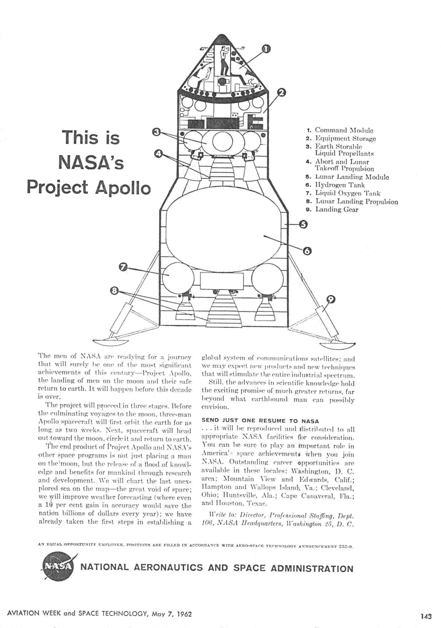
Actually, NASA’s initial plan was indeed to land on the Moon with a single, large, tall spacecraft: a concept known as tailsitter, since it would land on its tail (Figure 7.5-1).


Figure 7.5-1. One configuration of thel tailsitter conceived initially as a lunar landing vehicle, in a NASA advert in the magazine Aviation Week and Space Technology, May 1962. Source: Sven Knudson, Ninfinger.org.


This solution had the advantage of requiring a relatively simple trajectory: a direct flight to the Moon (known as direct ascent), with no complicated maneuvers for docking and extracting a lunar module, no need for part of the crew to transfer to the landing module and no rendezvous in lunar orbit that might go wrong upon returning from the lunar surface. For all these reasons it was the favorite plan among the NASA engineers in charge of developing the various spacecraft for the Apollo project.

However, a tailsitter had some very substantial drawbacks: for example, the astronauts would be required to land a very tall and therefore unstable vehicle (it was approximately 20 meters, or 60 feet, tall in the version shown in Figure 7.5-1). They would also have to land it without being able to see the lunar surface below them, due to the bulk of the spacecraft below them. In some versions they would have to resort to a periscope and fly while lying on their backs.

Once they had landed, they would have to climb down from the top of the spacecraft; not an easy feat in a rigid and bulky spacesuit, with the additional danger of falling (a fall on the Moon can be as fatal as on Earth, despite the lower gravity). Getting back in and loading the rock samples would entail a hazardous climb.

The main objection to a tailsitter was the fact that landing on the Moon with the entire spacecraft used for the trip from Earth, instead of using a dedicated bare-bones vehicle, would increase the mass involved, and therefore the fuel required, leading to the need for a rocket that was even larger than the already gigantic Saturn V.

For example, a tailsitter mission would require taking down to the lunar surface the entire crew and all the mass of the heat shield (useless on the Moon but necessary for return to Earth), as well as all the fuel, oxygen, water and food to be used on the return trip. This would require more powerful braking and descent engines, which would require more fuel, which in turn would require more powerful engines. All this mass, not needed on the Moon, would have to be lifted back from the lunar surface, requiring even more powerful ascent engines, and so forth.

Taking all the mass of a tailsitter on a direct flight to the Moon would have required a colossal rocket, the Nova (Figure 7.5-2), which didn’t exist yet and could not be completed in time for President Kennedy’s deadline. The only booster that could be developed in time was the Saturn V, which was relatively smaller.


Figure 7.5-2. The giant Nova booster (right) compared with the C-5, precursor of the Saturn V (center). Document M-MS-G-36-62, April 1962.


Mission planners also considered using a first Saturn V to launch an uncrewed tailsitter spacecraft into Earth orbit, followed by a second Saturn with the fuel. This was known as Earth Orbit Rendezvous (EOR) and was NASA’s favored plan for some time. However, it entailed two closely coordinated launches and a dangerous and untested transfer of fuel in space. It also required landing on the Moon, and especially lifting off from the Moon, with no external help, a spacecraft as large as an Atlas rocket, which on Earth needed roughly three thousand people to prepare it for launch.

An alternative option was to split the tailsitter into two separate vehicles: the main one would remain in orbit around the Moon and the secondary one would be a stripped-down, specialized Moon lander.

This approach reduced weight and fuel requirements so much (by about three quarters) that it allowed to launch the entire mission with a single Saturn V rocket. However, the savings came at the cost of a risky rendezvous in lunar orbit (hence the name Lunar Orbit Rendezvous or LOR), which entailed certain death for the moonwalkers if it failed. A high-stakes gamble, in other words, but a perfectly logical one.

The lunar orbit rendezvous plan wasn’t new: it had been conceived in 1916 by Russian spaceflight theoretician Yuri Vasilievich Kondratyuk. Nevertheless, NASA was very reluctant to take this perilous and untested path, although preliminary studies on various methods, including LOR, had been ordered. The agency continued to believe that it had to try the tailsitter method. It should be remembered that at that time nobody had ever performed a rendezvous with docking in space, even in Earth orbit, and therefore the concept of performing a rendezvous while orbiting the Moon was extremely daring.

In 1961, a relatively low-ranking aerospace engineer at NASA, John Houbolt (1919-2014, Figure 7.5-3), vociferous supporter of the LOR method, skipped official channels and wrote an impassioned letter to NASA’s associate administrator, Robert C. Seamans Jr., noting that he was “a voice in the desert” in arguing for the convenience, and indeed the need, to resort to this solution in order to meet the end-of-decade deadline.

His initiative led to a review of the LOR concept, which however was not not backed by NASA senior managers. But Houbolt’s persistence paid off: in July 1962 the obsession of an unknown engineer became NASA’s final plan for getting to the Moon.


Figure 7.5-3. John Houbolt in 1962. Source: NASA/LARC/Bob Nye.


John Houbolt’s crucial role in the success of the Apollo missions is often unknown to non-experts, but NASA celebrates him extensively. Here are some references if you want to know more about him:


7.4 How is it possible that everything went so smoothly?

IN A NUTSHELL: It didn’t. NASA went out of its way to give this impression, but the truth was quite different. Three astronauts died on the launch pad (Apollo 1). Apollo 13 suffered an explosion that scrubbed its lunar landing and almost killed the crew. Apollo 12 was struck by lightning at liftoff. Apollo 11 had a computer overload as it was landing on the Moon and lost control during rendezvous. Every mission had its significant malfunctions, equipment failures and close calls, and many crews were struck by nausea, vomiting and diarrhea, but all this wasn’t widely publicized.


THE DETAILS: Moon hoax theorists often express their sarcastic amazement at the perfection of the Apollo flights to the Moon. How is it possible that such incredibly complex and powerful machines, which pushed the envelope of 1960s technology, could work so flawlessly? And how could astronauts be so impeccably cool and professional on such life-threatening journeys?

Actually, this perfection is only an impression driven by superficial knowledge of the events and by the fact that the political importance of the lunar missions prompted NASA and the media to gloss over the errors and failures and the less dignified aspects of the endeavor. National prestige was at stake, so problems were played down in public. Some failures, however, were too big to be brushed under the carpet.

As a matter of fact, out of seven attempted Moon landing missions, one failed (Apollo 13). Three astronauts died on the launch pad (White, Grissom and Chaffee, Apollo 1). All the missions had problems that brought the crew close to disaster or abort. Here are a few examples taken from the technical mission reports. A more extensive list of the various critical and non-critical malfunctions that affected the various missions is in the Discrepancy Summary section of the Post-launch Mission Operation Reports.


Apollo 7

  • Water from the cooling systems pooled in the cabin, posing a serious danger in an environment crammed with electrical wiring.
  • The crew was plagued by a cold that blocked their nasal passages: a serious problem in spaceflight, because in weightlessness fluid accumulates instead of draining and blowing one’s nose can cause severe ear pain, and because during reentry, with their head enclosed in the helmet, the astronauts would be unable to clear their ears and therefore compensate for cabin pressure changes, with the risk of eardrum damage. Despite NASA’s strong disagreement, the crew performed reentry without wearing their helmets and suffered no physical consequences.
  • The Apollo 7 crew also refused orders from Mission Control, and commander Walter Schirra had no uncertain words about the unprecedented workload of the maiden flight of the Apollo spacecraft, speaking openly of “tests that were ill prepared and hastily conceived by an idiot” and declaring that he’d “had it up to here” and that his crew was “not going to accept any new games... or going to do some crazy tests we never heard of before”, as described in the book Apollo: the Epic Journey to the Moon, by David Reynolds. This was one of several underreported rebellions of spaceflight crews.


Apollo 8

  • The first crewed flight around the Moon was troubled by bouts of vomiting and diarrhea affecting the mission commander, Frank Borman, during the first day of flight, nearly forcing an early return home.
  • Three of the five spacecraft windows were fogged by sealant leaks, hindering viewing and lunar photography.
  • Water again formed dangerous pools in the cabin, just like on Apollo 7.
  • During the flight, Jim Lovell accidentally erased part of the computer’s memory, leading the inertial position measurement unit (IMU) to assume that the spacecraft was still on the launch pad and to automatically ignite the maneuvering thrusters to try to correct the problem. The crew was forced to compute and reenter the correct data by hand.


Apollo 9

  • Astronaut Rusty Schweickart vomited repeatedly due to nausea induced by weightlessness, forcing cancellation of the emergency procedure test (a spacewalk from the Lunar Module to the Command Module) and of the test of the lunar EVA spacesuit that he was scheduled to perform.
  • One of the maneuvering thruster sets of the command and service module failed due to a misplaced switch.
  • The Lunar Module tracking light failed: this was a crucial component, since the LM and the CSM had to maneuver and fly separately, up to 185 kilometers (115 miles) apart, in Earth orbit and then find each other and dock again, otherwise the two crewmembers in the LM would have died in orbit, unable to return to Earth. Rendezvous was achieved despite these failures thanks to the skill of the astronauts.


Apollo 10

  • When the ascent stage of the LM separated from the descent stage, just 14.45 kilometers (47,400 feet) above the lunar surface, an incorrect switch setting made the spacecraft spin wildly about two axes, coming dangerously to a so-called gimbal lock (loss of orientation of the navigation system). Astronaut Gene Cernan let slip a heartfelt “Son of a bitch!”, which was picked up by his open radio mike and transmitted live to world audiences back on Earth.


Apollo 11

  • During this first Moon landing, the Lunar Module’s computer, which was crucial for a soft touchdown, overloaded repeatedly.
  • The preprogrammed flight path for landing on the Moon would have taken the spacecraft to a boulder-strewn area, where landing and liftoff would have been prohibitive if not impossible. Only Armstrong’s manual intervention to change landing site, assisted by Aldrin, saved the mission.
  • As Armstrong and Aldrin descended to the Moon, the Lunar Module’s descent engine experienced extreme fluctuations due to the instability of the control software. The landing was almost aborted, as explained in detail in Tales from the Lunar Guidance Computer by Don Eyles.  
  • Radio communications in lunar orbit, after separation of the LM from the Command Module, were so poor and broken up that Armstrong and Aldrin in the LM didn’t hear the “go” to initiate descent to the Moon from Mission Control. Fortunately it was picked up by Michael Collins, in the Command Module, who relayed it to his colleagues.
  • After landing on the Moon, one of the propellant lines of the descent stage failed to vent correctly due to freezing, leading to a potentially explosive pressure buildup. Only Mission Control noticed the problem and was discussing it guardedly with the crew when it cleared itself up by thawing.
  • After the moonwalk, the astronauts realized that the knob of a circuit breaker required for arming the ascent engine was broken, probably because it had been struck by Aldrin’s backpack. If that circuit could not be operated, liftoff from the Moon would be impossible. Complicated workarounds were possible, but the astronauts improvised by using a felt-tipped pen to operate the failed breaker.
  • On returning from the lunar surface, when the LM docked with the command and service module, the slightly incorrect alignment of the two spacecraft triggered an uncontrolled rotation that the onboard computers both tried to correct, contrasting each other and worsening the spin. Only Collins and Armstrong’s skills allowed to correct manually the chaotic tumbling of the mated vehicles.


Apollo 12

  • The lightning bolt that struck the Saturn V during liftoff caused widespread instrument malfunctions and a total loss of meaningful telemetry. Only an unusual suggestion by John Aaron in Mission Control (the request to set “SCE to AUX”), radioed up to the astronauts, allowed them to restore telemetry and prevented the mission from being aborted immediately.
  • During the live TV broadcast from the Moon, the TV camera was pointed accidentally at the sun and its delicate sensor burned out, ending TV transmissions for the mission’s moonwalk.
  • At the end of the flight, during atmospheric reentry, the wind caused the command module to swing beneath its parachutes and the astronauts were subjected to 15 g of deceleration on impact; a camera fell from its holder and struck Alan Bean on his temple. Had it fallen slightly to the left, it would have caused a potentially fatal head trauma.


Apollo 13

  • As already mentioned, an oxygen tank in the service module ruptured explosively, depriving the astronauts of air and power reserves. It became necessary to use the LM as a lifeboat and return hurriedly to Earth after looping around the Moon. James Lovell had to align the navigation systems manually by star sighting.


Apollo 14

  • On the way to the Moon, the docking mechanism between the LM and the Command Module failed five times before finally working. This meant that it might fail again when the LM returned from the Moon, forcing the astronauts to perform a dangerous spacewalk to transfer from the LM to the Command Module, but the decision was made to go ahead with the landing nonetheless.
  • An errant solder ball in the LM’s general abort button caused the onboard computer to receive a false abort signal, which during lunar descent could have triggered an unnecessary emergency climb back to orbit, canceling the Moon landing: in the nick of time, NASA and MIT managed to write and send up instructions to reprogram the computer so that it would ignore the false signal.


Apollo 15

  • One of the three splashdown parachutes failed to open fully (Figure 7.4-1), leading to a violent impact with the ocean. The malfunction was probably caused by venting propellants, which could have caused all three parachutes to fail, with fatal consequences for the crew.


Figure 7.4-1. Apollo 15’s splashdown with a malfunctioning parachute. Photo AS15-S71-42217.


Apollo 16

  • The command and service module main engine, crucial for returning to Earth, reported a malfunction while the spacecraft was in orbit around the Moon. The Moon landing was almost scrubbed.

Apollo 17

  • On the Moon, one of the astronauts unintentionally broke one of the fenders of the Rover electric car (LRV) and the moondust kicked up by the wheels fell copiously onto the vehicle, causing mechanical and thermal problems. The astronauts were forced to improvise repairs on the lunar surface.
  • During ascent from the Moon, Mission Control lost radio contact with the Lunar Module and received no telemetry for four full minutes. The Conmand Module pilot had to repeat everything that the LM astronauts wanted to report to Earth.